Cisco ASA – A/S Failover
Description
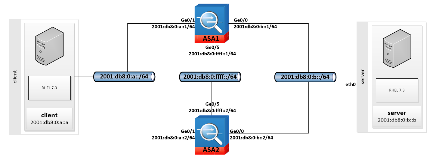
Lab Schema

Preconfiguration
1a. Configure IPv6 (ASA1)
Configure IPv6 address on both inside and outside interfaces. DO NOT configure GigabitEthernet0/5 (interface which will be used for asa-2-asa communication)
Interface GigabitEthernet0/1
ipv6 address 2001:db8:0:a::1/64
Interface GigabitEthernet0/0
ipv6 address 2001:db8:0:b::1/64
1b. Configure IPv6 (ASA2)
Configure IPv6 address on both inside and outside interfaces. DO NOT configure GigabitEthernet0/5 (interface which will be used for asa-2-asa communication)
Interface GigabitEthernet0/1
ipv6 address 2001:db8:0:a::2/64
Interface GigabitEthernet0/0
ipv6 address 2001:db8:0:b::2/64


2. Check your IPv6 configuration
ping 2001:db8:0:a::1
ping 2001:db8:0:a::2
ping 2001:db8:0:b::1
ping 2001:db8:0:b::2

Failover configuration (CLI)
3. Configure failover (CLI)
Following will be configured on ASA1:
failover lan unit primary
interface GigabitEthernet0/5
no shutdown
failover lan interface asa-2-asa GigabitEthernet0/5
failover interface ip asa-2-asa 2001:db8:0:ffff::1/64 standby 2001:db8:0:ffff::2
failover key **********
no failover ipsec pre-shared-key
failover link asa-2-asa
failover
Failover configuration (ASDM)
4. Start Wizard
Execute HA and S Vizard. Select Active/Standby Failover as a prefered configuration

5. Compatibility check
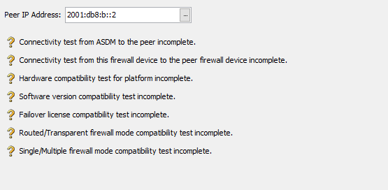
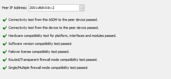
ASDM will check if both devices are compatible. No errors/non critical errors will allow to continue configuration process


6. Configure communication link
Configure communication link which will be used to synchronize both units. This interface will be dedicated only for failover.

7. Configure stateful failover
Stateful failover will allow to keep connections after active device malfunction. Both separate interface and existing communication link can be used.

8. Configure standby address
Standby address will be available on standby (secondary) unit. Check "monitor" to decide which interfaces will be responsible for checking second device availability.

9. Review configuration
Review configuration before sending it into second device

10. Synchronization
Wait 1 min fo full synchro (it should be ready sooner, so feel free to skip waiting and exit into ASDM).


11a. Check failover status
Check status on active device:
sh failover history
sh failover state


11b. Check failover status
Check status on standby device:
sh failover history
sh failover state


12. Modify Failover Criteria (optional)
- The frequency of sending keepalive messages via control link is defined as Unit Failover
- The frequency of sending keepalive messages via monitored links is defined as Monitored Interfaces
- When failover control link is down, device will start to probe data interfaces (marked as monitored) after Unit Hold Time
- No keepalive message on monitored interfaces for Interface Hold Time will mark them as failed.

Test Area
13. Test failover (ping6 from 2001:db8:0:a::a -> 2001:db8:0:b::b)
Test failover using ping6. Option -D will add timestamps into statistic
ping6 -D 2001:db8:0:b::b
In our scenario, standby device become active in 8 seconds.

14. Test failover (standby device)
Check failover state on standby device before and after malfunction
- Second unit is in Standby Ready state,
- First unit is no longer available (power off). Second unit is Switching to Active
- Second unit is in Active state.

